Nuke Quicktip: Nuke UV texturing

I See You Drake GIF by NBA

Hey, you! Long time no see… Hope you’ve been good.
Today I am going to teach you how to use a uv pass from a 3D render to add some texture to your subject. Let’s get stuck in!

I will use one of my personal projects as an example.
Recently, I went out to shoot a few plates with the intention of integrating a CGI car into one of them.

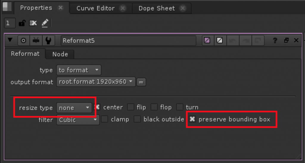
After the careful process of gathering all shoot data, picking the proper take, tracking/match-moving it and creating a full lens distortion and overscan pipeline for it, it was time for the CG side of things. That’s when I called in a friend of mine to lend a helping hand.

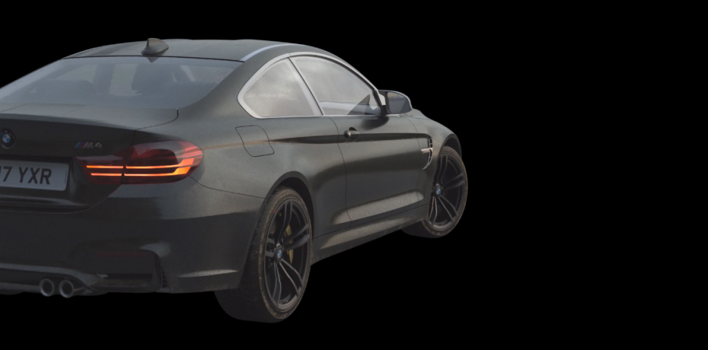
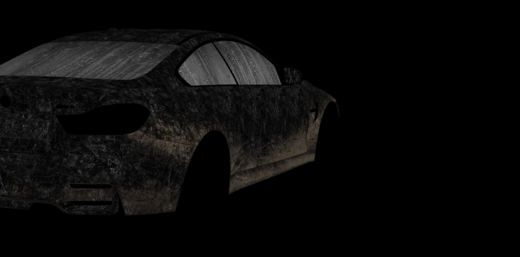
We started with just one frame to save render times. This way we checked that everything was working visually before setting up the whole sequence to render.

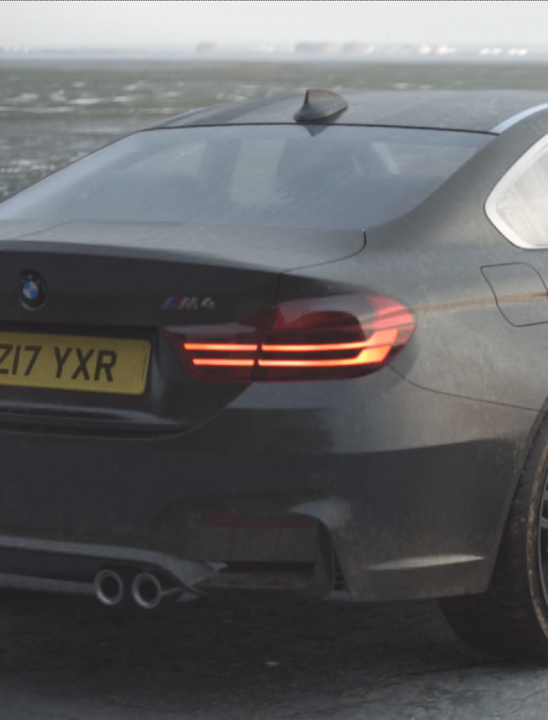
With a few basic adjustments, the car looked good! Nonetheless, I wanted to make it look even more convincing, so I started to think as if the car was actually there.

Hypothetically, by the time the car had driven over sand, near water onto this sort of brick podium, it definitely won’t be “brand spanking new”.

Therefore I thought that adding a few mud splashes, dry water drips on the bodywork and condensation on the windows. This would make it look more natural and less like a showroom car toed on set for a commercial shoot.

Let’s not forget the set interaction as well. If the wheels are dirty, you can bet that they would leave tire marks on the floor.

With all of this, you might think… Send it back to 3D

Episode 15 No GIF

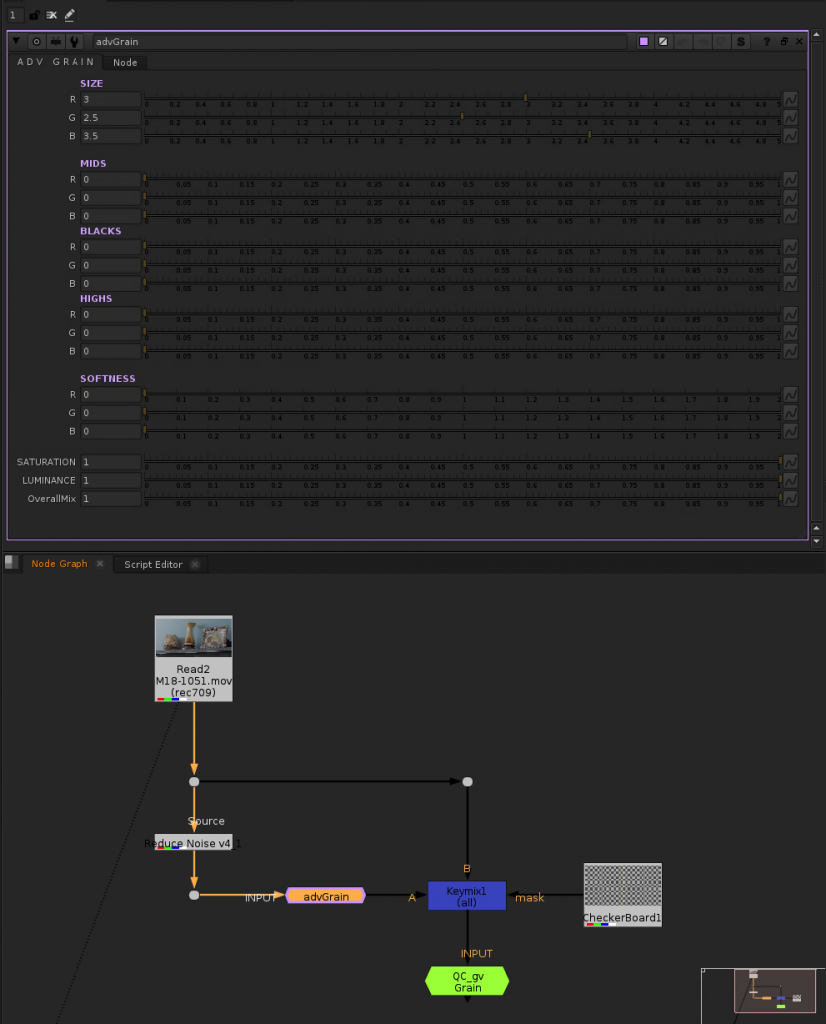
No way! We can easily do this in Nuke with UV passes.
For this to work, you need to make sure that your 3D model is properly UV unwrapped.

This will give us complete flexibility over where and what type of texture we want. As well as minimising wasted time spent on rendering back and forth.

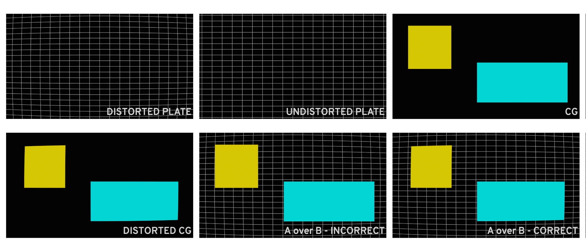
To start you will need exported UV nets of your 3d model. They should look something like this.

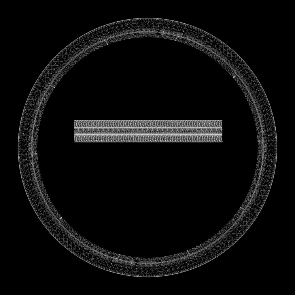
You can now gather your textures and position them roughly where you want them (checking by merging them over your nets),
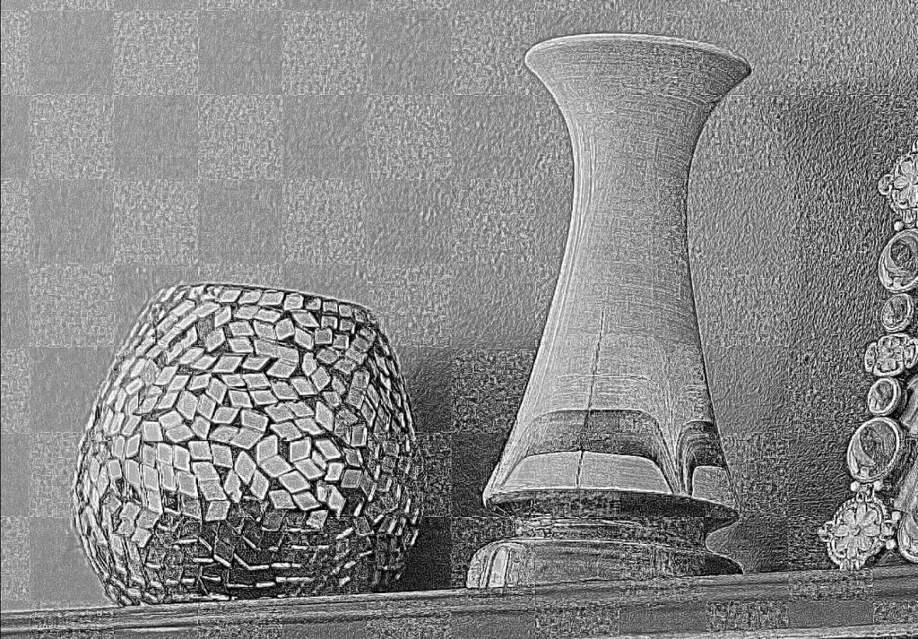
Once positioned, stick them through a STMap node with the UV pass as the “stmap”.

Here is the setup in my example

To cut out only the areas that you need to texture, I recommend multiplying the result by IDs or cryptomattes.

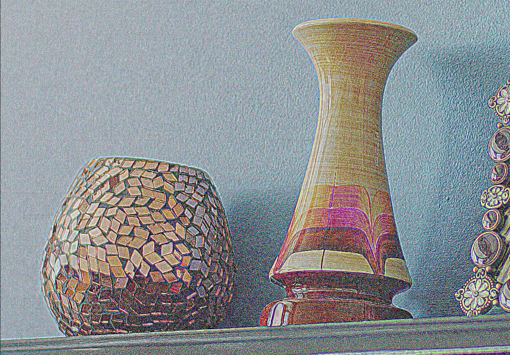
After layering a few textures I achieved something like this.

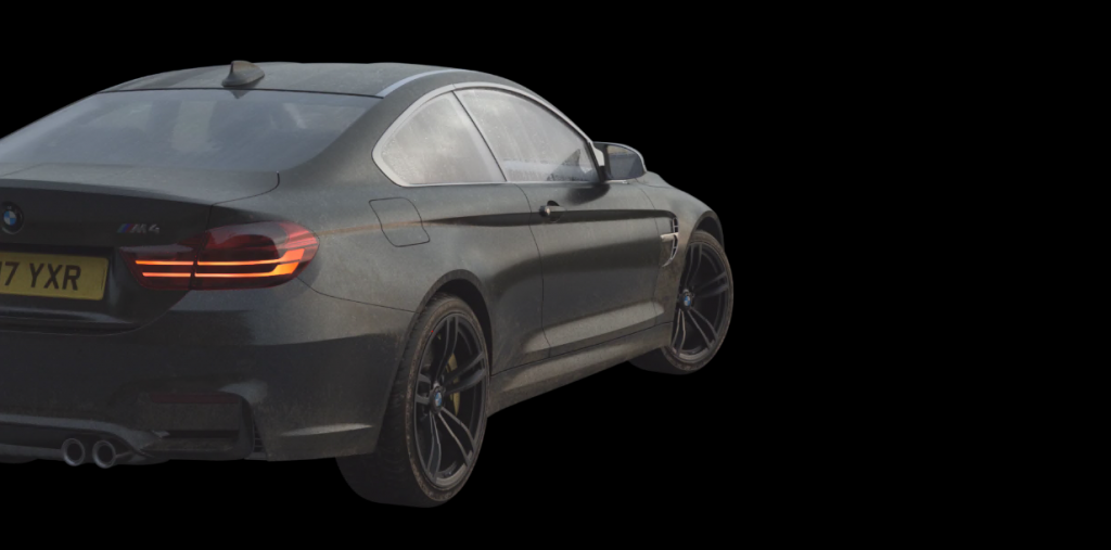
Pretty neat right! Of course, you don’t have to limit yourself to just textures, you could even add some decals. The world is your oyster…

I hope that this post helped you on your journey to becoming a more rounded compositor as well as strengthening your relationship with your fellow 3D artists! Catch you later.

Im Out See Ya GIF

Nuke Quicktip: Lensing Pipeline with 3D

So you have just realised that when applying optical lensing to CG with no overscan, the result will be cropped. This because there are no pixels outside the bounding box to compensate for the distortion.

You have also realised that some 3D programs do not have an “overscan” option when rendering, thus making the process quite tedious.

Well, today I am going to teach you how to always get perfectly accurate overscan in any 3D program. This achieved with a little bit of maths.

Thank U Reaction GIF by BROCKHAMPTON

Above all, a little background on lensing and distortion. Don’t worry I got you!

All camera lenses in the real world create lens distortion. Cameras in CG scenes don’t create this artefact. We apply lensing artifacts to CG in post to better integrate it to the footage that was shot.

A barebones distortion pipeline should look something like this:

• The scan, split into a separate pipe where it gets undistorted and tracked.

•match-moved patches/CG etc. with the tracking data, distorted then merged over the original (distorted) scan.

The industry standard to un-distort and re-distort are STMaps. Usually obtained by analysing lens grids / charts on a “per lens” basis.

Never un-distort to re-distort the whole plate as double filtering will take place. This heavily degrades the image quality of the scan.

Enough theory about lens distortion, let’s get into the practical pipeline.
First of all, we will need a few things.

These are:

– The parameters of your match-moved camera, that should match the real-world parameters of the camera used on set. Specifically, we will need the focal length and sensor size (h.aperture & v.aperture).
In my case, the focal length is 35mm, and the size of the APS-C sensor of my camera is 22.3 x 14.9.

– The resolution of your distorted/original plate and of the undistorted plate.

With this data, we will calculate how much we need to increase the field of view of our 3D camera relating to the amount of overscan we need. In other words calculating our new sensor size, specifically horizontal aperture and vertical aperture.

We achieve this by dividing the height and width of the UD Plate by their respective of the original plate. Obtaining a percentage increase.

With this percentage increase, we can now calculate our new sensor size.

See workings below

In our preferred 3D program, keeping everything else in our scene the same, we can change the resolution in our render settings to the UD plate, and input the new H & V.aperture values in our 3D camera (in Maya, in the “film back” settings).

You will probably have noticed that our camera seems to have moved backwards in the Z-axis. In reality, the field of view has changed to compensate for the distortion that will be applied later on.

This ladies and gentlemen is called overscan. Congrats! You did it.

In Nuke, all you have to do is reformat your render layer to the original plate resolution before merging over. Additionally making sure that you “preserve b-box” and set the “resize type” to none.

When you apply your lens distortion through a proprietary node, STMap or any other preferred method, you will notice that your distorted render will perfectly match the resolution of your original plate. Boom!

I hope this was of use to you.
Catch you on the flipside…

Im Out GIF by M&M’S Chocolate

QC Toolset for Nuke

Welcome Back GIF

Welcome back, my friends. In today’s blog-post, I am going to share my QC toolset for Nuke that will for sure help you with quality controlling your work.

The toolset will benefit you during the QC stage of your work and consists of three main nodes.

gv_QC Toolset Overview

The first node is an all-round QC tool that you plug in under the work you want to check. This enables you to view your work exposed down by 3-stops, up by 3, with visible grain etc. You know… all that standard good stuff.
If you need to do some px f-ing, you can even examine each quadrant separately. Also, don’t forget to check those corners!

gv_QC Toolset Matte Checker

The second tool is a stripped-down roto matte checker. (if you expand it you will realise it’s just a constant key-mixed over your input through a matte). Having said that, it’s highly useful when roto-ing and gets the job done.

The last tool is a roto checker similar to the one above but on compositing steroids.
With this neat little node, you can check your mattes through a coloured overlay, over a solid background and more. It also lets you create shape outlines in case you want to demonstrate your matte shapes for showreel purposes.

gv_QC Toolset Roto Assist

If you want to give this a crack, download the gv_QC Toolset for Nuke below. (paste the context of the .txt into your Nuke node graph, then create a new toolset with the group highlighted).

Enjoy!

Bears Hello GIF

Nuke Quicktip: Match the Grain

Wassup! It’s me again. Back with another Nuke Quicktip.
Today I am going to show you how to match the grain of a scan in Nuke. And a neat little trick to make your life easier when matching.

Whats Up Flirt GIF by Nick Cannon

The principle of the trick is to key-mix the denoised plate that is being re-grained over the original through a black and white checkerboard. The way we know the grain is matched is when we cannot distinguish individual squares.

In practice, following my re-grain setup we want to set-up a few nodes at the top of our tree.

match the grain setup
Make sure the checkerboard is solid black and white

Instead of my “advGrain” tool, you can use “AdvancedGrain“, “L_Grain” or even a standard “Grain” Node. I prefer going through the re-grain process focusing on blacks, mids and highlights in each channel of the RGB.

Now that we have our nodes set up, we can start to match the grain.
Viewing the “Grain QC” node, zero out all the properties. Now start matching the blacks in the red, green and blue channel (going back and forth if needed).

matching the grain demo

Continue by matching the mids in each channel, followed by the highs as well as any other necessary adjustments.

Before any re-graining takes place, viewing your channels should look something like this.

denoised over grain footage

When you cannot distinguish defined squares when viewing your input, you know you have matched the grain properly.

matched grain

Now, all you have to do is duplicate this grain node and put it wherever you are applying grain in your script.

Happy Season 1 GIF by Rick and Morty

Nuke Quicktip: CurveTool for light variation

One of the worst enemies of cleaning up offending objects from a scan is dynamic lighting; lighting that changes colour and/or intensity throughout the duration of the shot. Luckily, Nuke comes equipped with a smart little node called “CurveTool”.

If using a transform masked node is not an option, your first instinct would be to animate grades to match the patches to the lighting change in the scan.

Good Morning Help GIF by Satisfied Customer

Here is where I reveal to you the “CurveTool”. This node can be used to analyse an area there is a change in luminance, chrominance or both.

We adjust the sampling box to the desired area, keyframing if needed, and click go to analise the range we define.

CurveTool Properties

We then feed the information obtained from the CurveTool “IntensityData” to a multiply using the following expression in all three channels:

CurveTool Intensity Data Expression

“CurveToolName”.intensitydata/”CurveToolName”.intensitydata(patch sample frame)

The above expression divides the intensity data of the curve tool by the intensity on the chosen frame. This difference in colour is applied to the patch.

In practice, it would look something like this; where the curve tool analyses an area near the offending object for lighting change (could be useful to blur the scan before analysing, to minimise imperfections) then feeds the data to a multiply wich will grade the patch according to the “intensitydata” difference from the held frame and the current frame of the scan.

CurveTool application example

This would be the result.

Whilst the compers that think they are top dog sit keyframing their grades for an entire day, you’ll sit there like it was a piece of cake.

Paul Rudd Whatever GIF

If you wan to read more into the math behind a grade node in nuke click the button below!

Credit
Tom Luff
VFX Supervisor