So you have just realised that when applying optical lensing to CG with no overscan, the result will be cropped. This because there are no pixels outside the bounding box to compensate for the distortion.
You have also realised that some 3D programs do not have an “overscan” option when rendering, thus making the process quite tedious.
Well, today I am going to teach you how to always get perfectly accurate overscan in any 3D program. This achieved with a little bit of maths.
Above all, a little background on lensing and distortion. Don’t worry I got you!
All camera lenses in the real world create lens distortion. Cameras in CG scenes don’t create this artefact. We apply lensing artifacts to CG in post to better integrate it to the footage that was shot.
A barebones distortion pipeline should look something like this:
• The scan, split into a separate pipe where it gets undistorted and tracked.
•match-moved patches/CG etc. with the tracking data, distorted then merged over the original (distorted) scan.
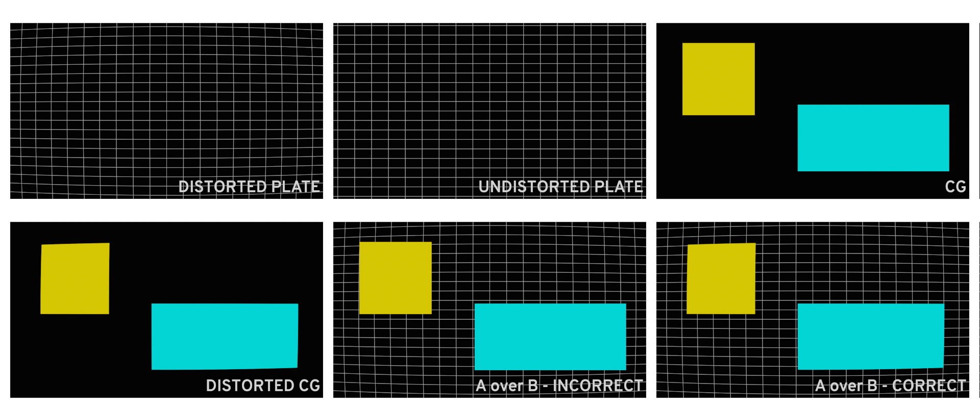
The industry standard to un-distort and re-distort are STMaps. Usually obtained by analysing lens grids / charts on a “per lens” basis.
Never un-distort to re-distort the whole plate as double filtering will take place. This heavily degrades the image quality of the scan.
Enough theory about lens distortion, let’s get into the practical pipeline.
First of all, we will need a few things.
These are:
– The parameters of your match-moved camera, that should match the real-world parameters of the camera used on set. Specifically, we will need the focal length and sensor size (h.aperture & v.aperture).
In my case, the focal length is 35mm, and the size of the APS-C sensor of my camera is 22.3 x 14.9.
– The resolution of your distorted/original plate and of the undistorted plate.
With this data, we will calculate how much we need to increase the field of view of our 3D camera relating to the amount of overscan we need. In other words calculating our new sensor size, specifically horizontal aperture and vertical aperture.
We achieve this by dividing the height and width of the UD Plate by their respective of the original plate. Obtaining a percentage increase.
With this percentage increase, we can now calculate our new sensor size.
See workings below…

In our preferred 3D program, keeping everything else in our scene the same, we can change the resolution in our render settings to the UD plate, and input the new H & V.aperture values in our 3D camera (in Maya, in the “film back” settings).
You will probably have noticed that our camera seems to have moved backwards in the Z-axis. In reality, the field of view has changed to compensate for the distortion that will be applied later on.
This ladies and gentlemen is called overscan. Congrats! You did it.
In Nuke, all you have to do is reformat your render layer to the original plate resolution before merging over. Additionally making sure that you “preserve b-box” and set the “resize type” to none.
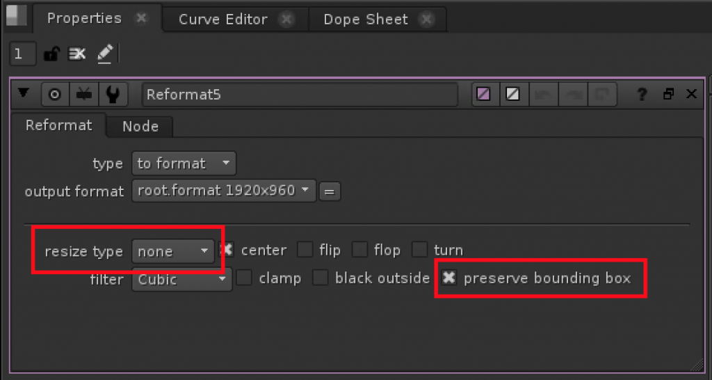
When you apply your lens distortion through a proprietary node, STMap or any other preferred method, you will notice that your distorted render will perfectly match the resolution of your original plate. Boom!

I hope this was of use to you.
Catch you on the flipside…